
|
|
HOME | Equipment | Stamping | Services | Quality | Contact Us |
| CAD | Wire EDM | CNC Mill | Process | Tooling | Parts |

Here at Gregg Tool & Die we use a LAN (Local Area Network) to share most of the information between the various systems. When a CAD print is completed some of the information may be sent to another system for implementation. If the work is to be done in one of the CNC mills then that section of the print will be transferred to our CAM software, PROCAM®. The CAM software gives the operator the ability to define a "tool path". The tool path is the set of instructions to the mill about the tool, its speed, and its direction with respect to the work piece.
One of the things to consider about a conventional mill is that the specifications of the work piece are typically right angle dimensions. For example, a die section might be a block having a constant width, height, and depth. In most cases this is adequate. Occasionally some part of the die will be required to form the product material into a 3D surface. If the surface is composed of complex curves this can pose a quite considerable problem. For the sake of discussion assume we wish to construct the following surface:
It would be impossible to create this part on a regular mill, or even "dimension" the print for the shop floor! A CNC mill can do this type of work because most of the commands from the computer are a series of X,Y,Z coordinates with associated movements.
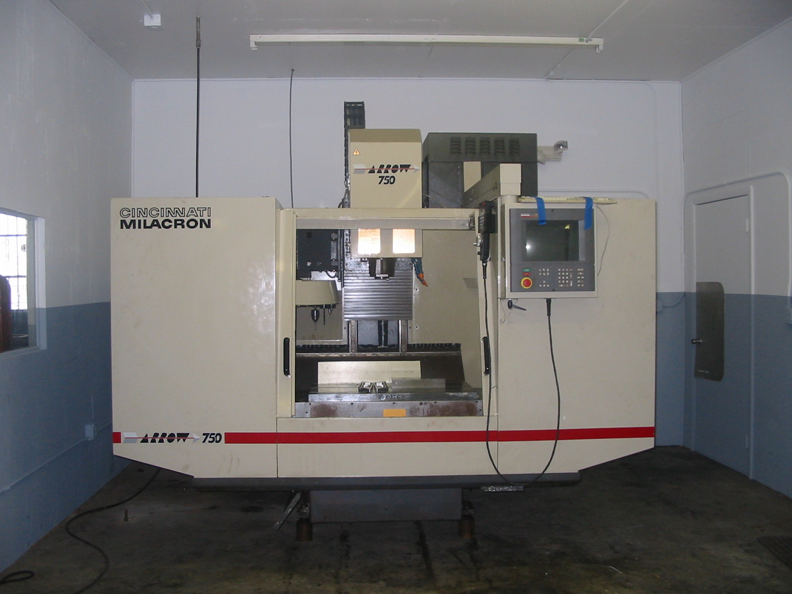
One of our other CNC mills is shown below. This is an Arrow 750, made by Cincinnati Milacron.

Below is a mold done on the CNC mill.
